¶ Replacement of Copper sleeve
¶ When to Replace
Severe wear and tear, or the after-sales or technical support personnel suggest replacement.
¶ Video Guide
Click to Jump IR3V2 Replacement of the Copper sleeve
¶ Replace Guide
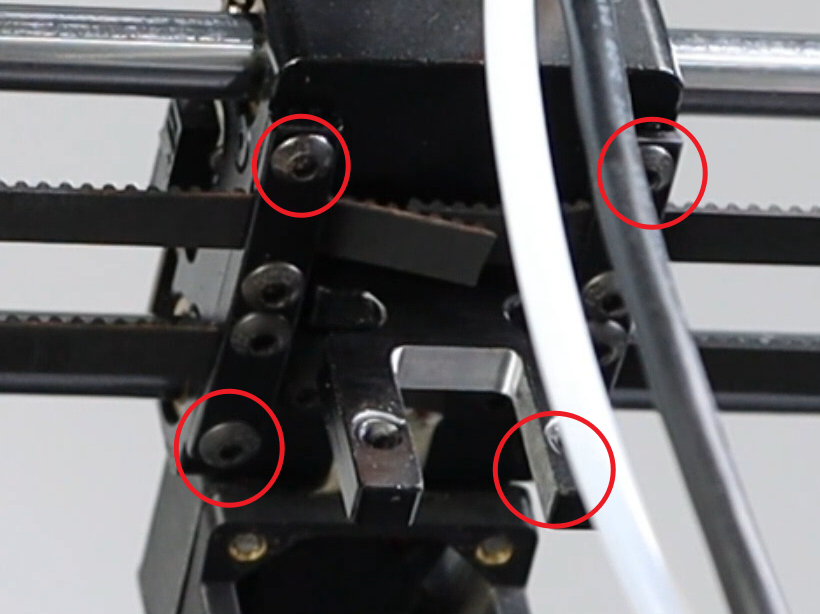
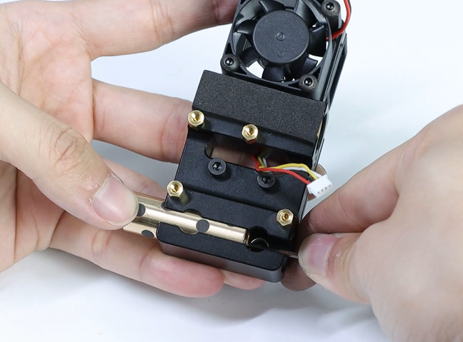
- Refer to the video guide, After removing the print head, loosen the four screws at the bottom.
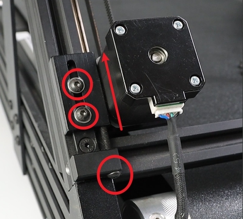
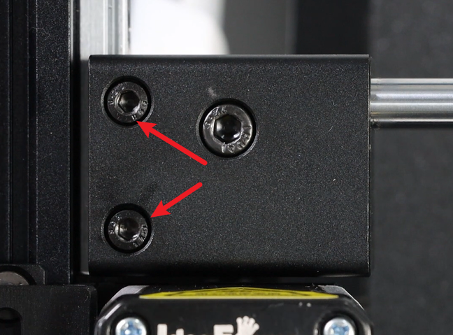
- Loosen Three screws on each of the left and right motors, then move the motors to the topmost position. The picture below shows the left motor.
- Remove the synchronous belt from the slot.
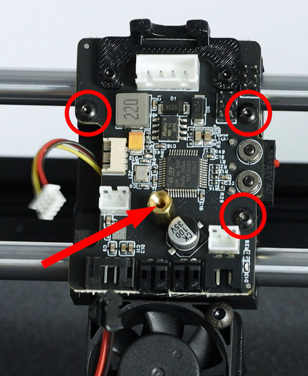
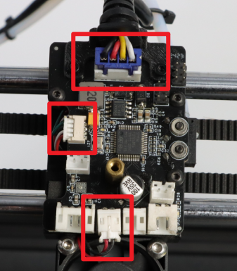
- Unplug the cables on the toolhead mainboard.
- Remove the M2.5X4 hexagonal screws and copper pins on the motherboard, and then remove the motherboard.
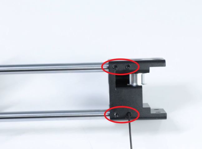
- Remove the two M4X5 socket head cap screws on the front side of the fixing block, and there are another two on the back side. Note: The same procedure applies to the right fixing block.
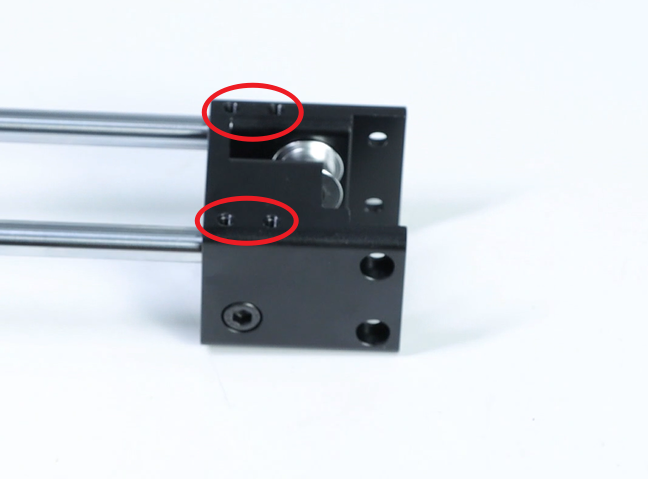
- Remove the X-axis, and loosen the KIMI screws on the fixing block.
- Remove the X-axis slider, loosen the flat head screws on the top (2 M2.5x6 flat head hexagon screws on either side), and tear off the sound insulation foam.
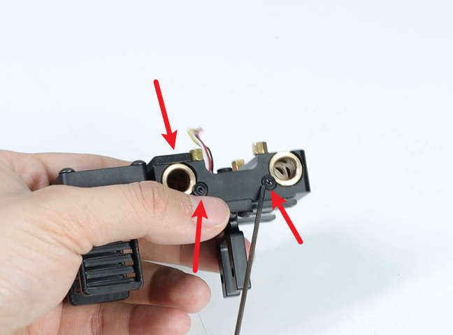
- Remove the copper sleeve. Note: Under the copper sleeve that is not fixed with sound-absorbing cotton, there is a spring. Be careful when removing it.
- Insert the new copper sleeve and stick it back onto the sound insulation material. Lock the flat head screw in place. Note: The rear copper sleeve should be pressed down on the spring first, then the copper sleeve should be installed.
- Reinstall the X-axis slider and the X-axis bracket
- After tightening the screws of the KIMI, check if the X-axis slider movement is smooth. If it is sluggish, rotate the two optical axes until the X-axis slider can move smoothly.
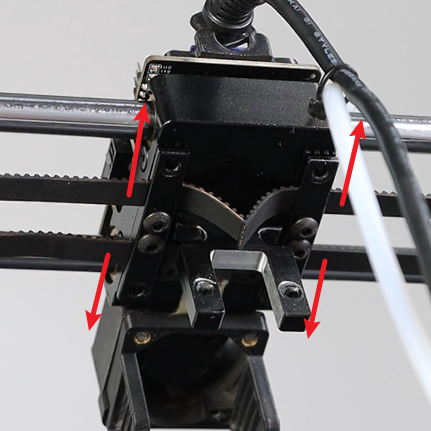
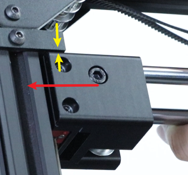
- Reinsert the entire X-axis into the Y-axis slider. Align the screw holes of the X-axis fixing block with the fixing holes of the Y-axis slider, then lock in the screws (8 M4×5 cup head hexagonal screws). At this point, do not tighten yet. Push the X-axis fixing block to both sides to make the X-axis fixing block tightly adhere to the Y-axis slider. Then move the X-axis to the top. Note that there should be no gap between the two fixing blocks and the upper part (as indicated by the yellow arrow in the picture). Press down on the bottom of the fixing block and then lock the screws (pay attention to the direction of the slider, the 3015 fan faces the conveyor belt).
 Move the X-axis slider to check if it is smooth. If it is smooth, lock the base screws. If not, loosen the screws on the other side and then rotate the two optical axes. Then continue to move the X-axis slider until it becomes smooth. Finally, lock the Set screws.
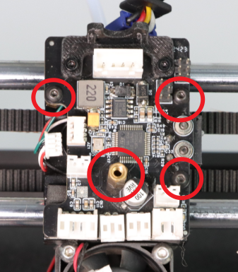
- Reinstall the locking screws (M2.5×4 flat-head hexagonal screws, 3 pieces) on the print head motherboard and the copper posts (M2.5×12 + 4).
- Reference Replacement of the synchronous belt on the x,y axis, After arranging the synchronous belt properly, insert it into the synchronous belt fixing slot and lock it with screws (4 M3×5 head hexagonal screws). Tighten the loosened screws on the XY motor, and straighten the synchronous belt.
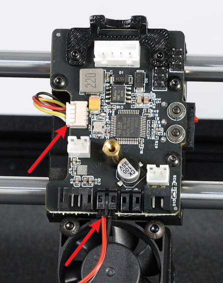
- Insert the strain gauge terminals, the 3015 fan terminals and the mainboard line terminals.
Assemble the toolhead back together, After turning on the machine, click the “Auto Leveling” button.