¶ Replacement of conveyor belt
¶ When to Replace
Most of the conveyor belt has been scratched and the base color is exposed;
Even after being tightened and heated, the welds on the conveyor belt still bulge;
The conveyor belt has cracked and is affecting the printing.
¶ Video Guide
Click to Jump IR3V2 Replace the conveyor belt Guide
¶ Replace Guide
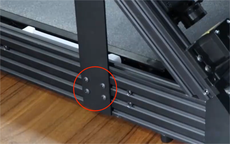
- Unplug the cables of the XY servo motor, the travel detection sensor, and the connection lines of the mainboard. Loosen a total of 8 M5×20 hexagonal head screws on both sides.
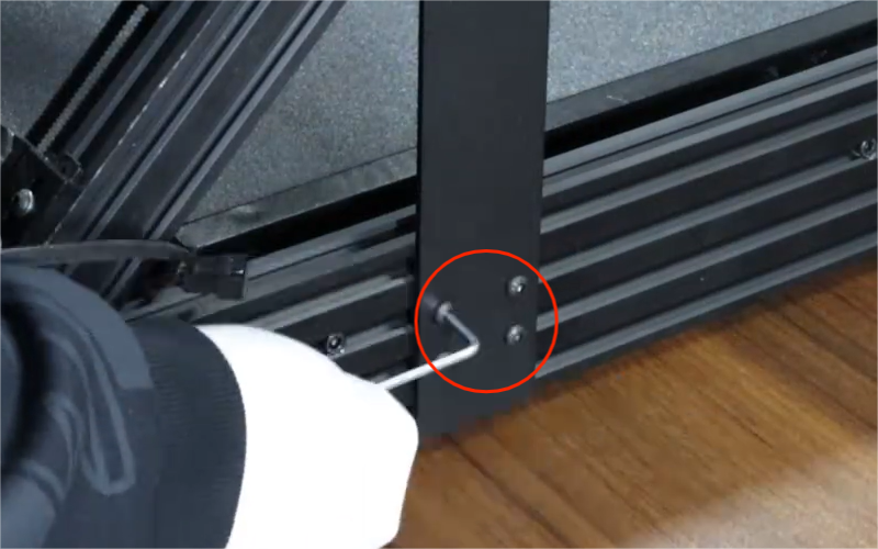
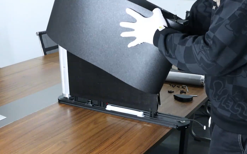
- Hold the upper frame to prevent it from falling off. Then unscrew the two M5×14 socket head hexagon screws that connect the upper frame to the base.
- After removing the XY-axis frame, remove the baffles and the 4 M4×6 hexagonal screws and T-type nuts on the baffles respectively.
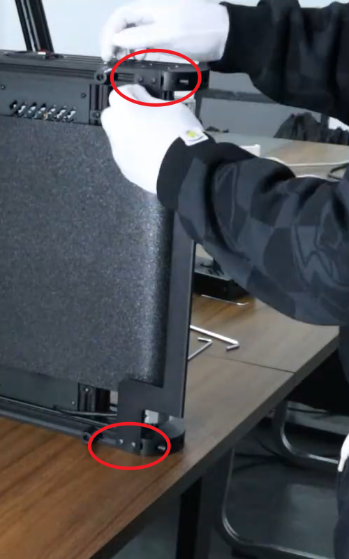
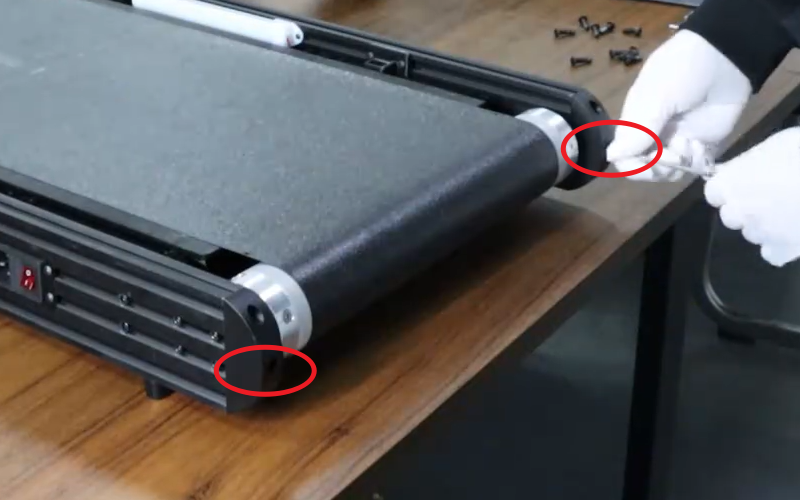
- Loosen the two M5X50 hexagonal screws located in the end cover of the front roller of the conveyor belt until the front roller is pushed back to its final position.
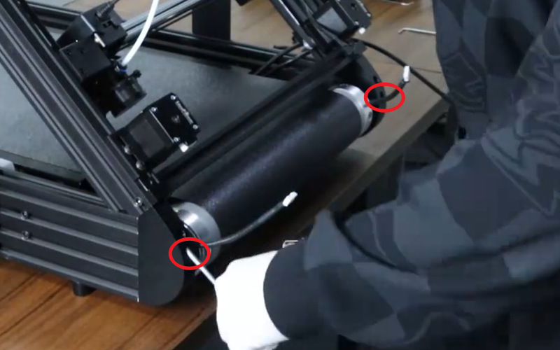
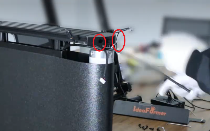
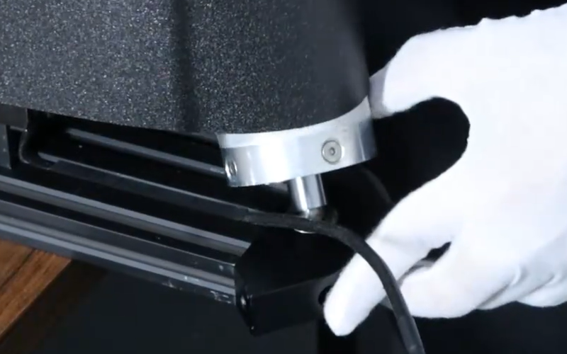
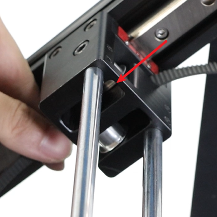
- Place the platform sideways, loosen the 2 M5×20 socket head hexagon screws on the bearing seat, hold the rear drum in place, then remove the bearing seat on the upper side of the drum (after removing the drum, be careful as the conveyor belt might suddenly catch your hand).
- Remove the conveyor belt and put on the new one.
- Tighten the conveyor belt, insert it into the rear drum and align it with the bearing below, then cover the bearing housing.
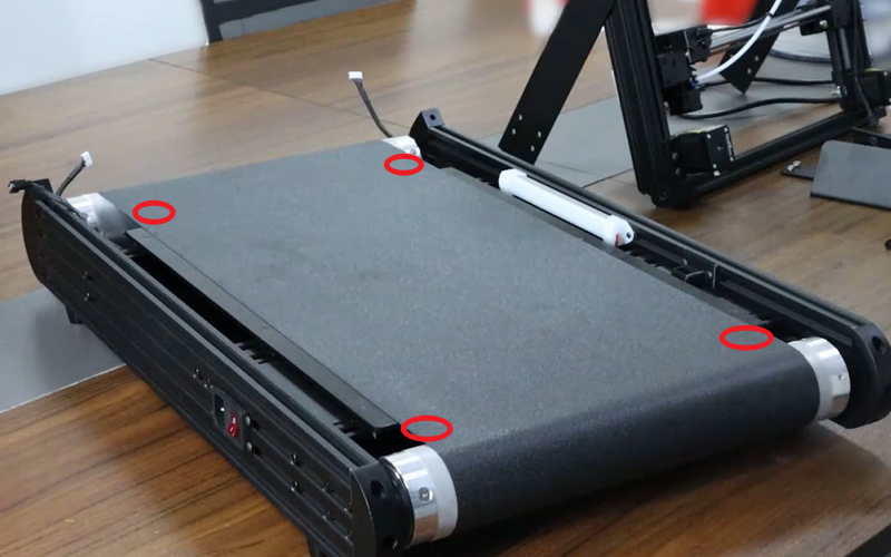
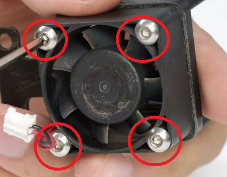
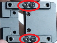
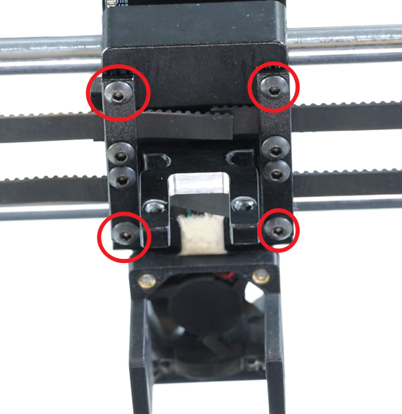
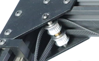
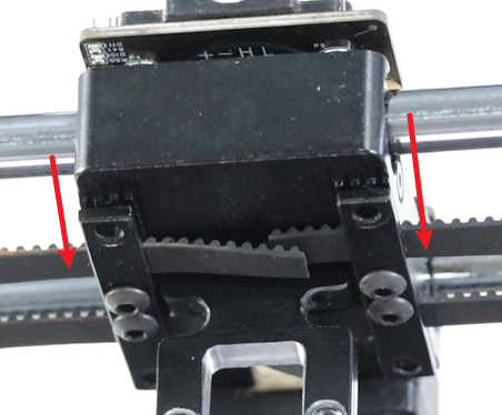
- Retighten 2 M5×20 cup head hexagonal screws, and tighten the 2 M5X50 cup head hexagonal screws that were loose at the front drum until the conveyor belt is flush without bulging. Press at the four points in the picture, continue to tighten the 2 screws until it requires a little force to press down, and make the conveyor belt in the appropriate tension state.
¶ Toolhead related
¶ Assembly and Disassembly the Toolhead
Click to JumpIR3V2 Assembly and Disassembly Tool Head Guide
¶ Nozzle replacement
¶ When to Replace
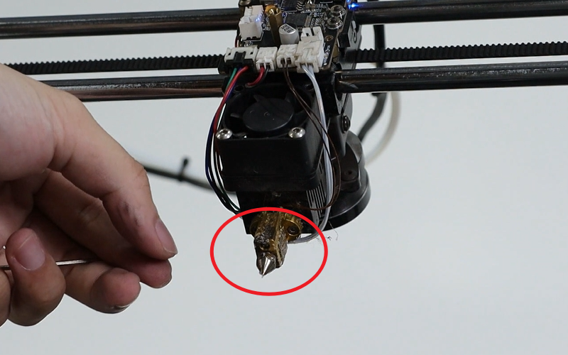
Nozzle clogged; nozzle severely worn and causing material leakage.
¶ Video Guide
Click to JumpIR3V2 Nozzle replacement Guide
¶ Replace Guide
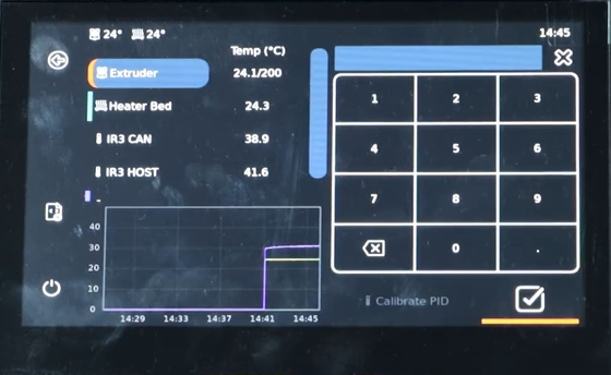
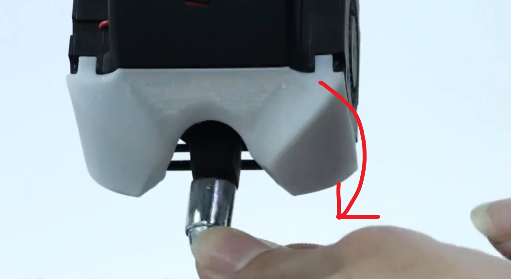
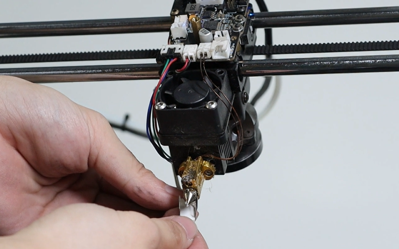
- Heat the nozzle to 200℃ and then unscrew the nozzle using a socket wrench.
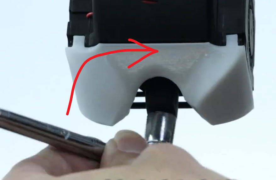
- Insert the new nozzle into the socket wrench, align it with the heating block threads and tighten it.
¶ Replacement of heating block
¶ When to Replace
Heating block clogging
¶ Video Guide
Click to Jump IR3V2 Assembly and Disassembly ToolHead Guide
¶ Replace Guide
- Reference Nozzle replacement After removing the nozzle,
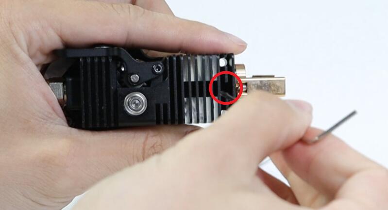
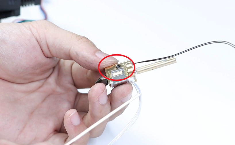
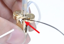
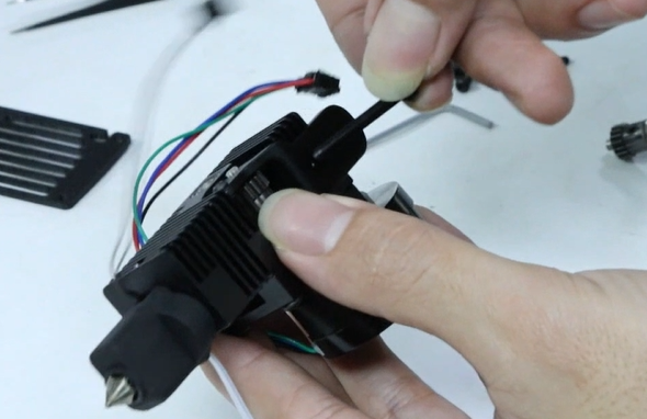
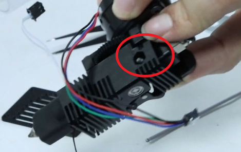
Remove the toolhead, Loosen the Set Screw at the top of the front end.
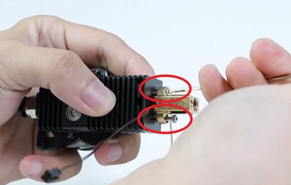
- Unscrew the two silver screws at the front.
-
Take out heating block,Reference Replacement of heating element and Replacement of Thermosensitive element Take out the heating element and the Thermosensitive element, attach them to the new heating block, and then insert them into the main body of the toolhead.
-
Lock the two silver screws and the corresponding Set screw, then reinstall the print head into the machine. Heat the nozzle, tighten the nozzle. ReferenceIR3V2 Assembly and Disassembly Tool Head Guide, Install the toolhead back.
¶ Replacement of heating element
¶ Video Guide
Click to Jump IR3V2 Replacement of heating element Guide
¶ Replace Guide
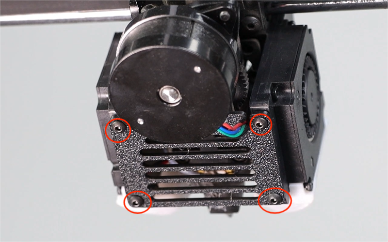
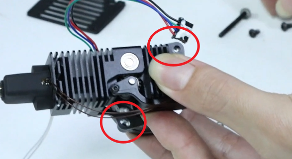
- Disassembly the flat-head screws at the top of the print head and take off the four cap-head screws at the bottom of the print head housing.

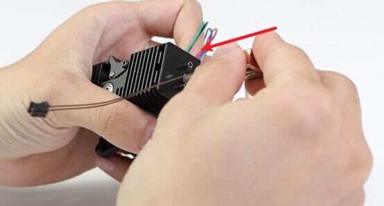
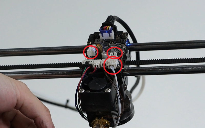
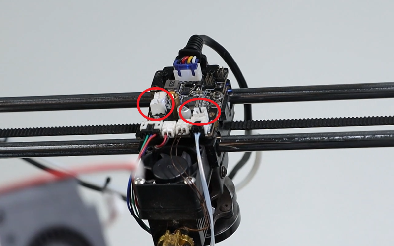
- Remove the outer shell, unplug the terminal of the blow mold fan, pull out the terminal of the heating plate, and take off the silicone sleeve of the print head.
- Use the forceps to pry open and remove the fixation clamp.
- Install the new heating sheet, and then fix the clamp back to securely attach the heating sheet (pay attention to the direction of the clamp, and the V-shaped pressing plate that presses the heating sheet should have an opening facing the nozzle). When the clamp is fixed, the heating sheet should not be able to move, should be tightly attached to the heating block, and the clamp should hold the protrusions on both sides of the heating block.
- Insert the heating element terminal back in.
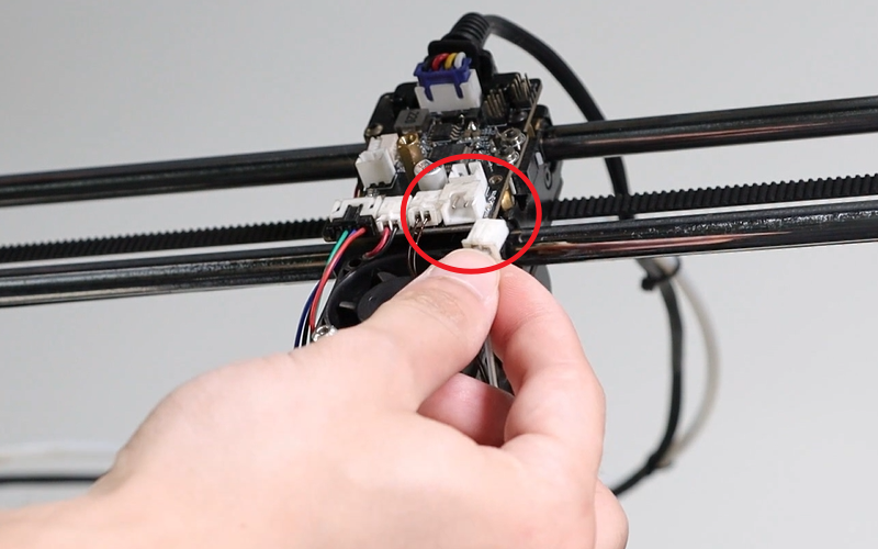
- Insert the blow mold fan terminal back in, be careful not to insert it incorrectly.
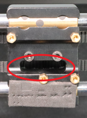
- Insert the toolhead housing into the recess of the mainboard communication line.


- Tighten the flat head screws on the top, reinstall the rear cover plate and tighten the four screws at the bottom. Insert the silicone sleeve (pay attention to the direction of the silicone sleeve; the slanted part at the nozzle end should face downwards).
¶ Replacement of Thermosensitive element
¶ Video Guide
Click to Jump IR3V2 Replacement of Thermosensitive element Guide
¶ Replace Guide
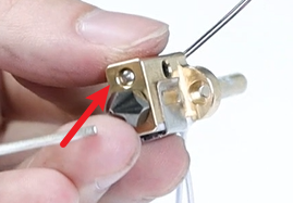
- Reference Replacement of heating block after removing the heating block, loosen the Set screws on the heating block.
- Take out the thermal element and insert a new one.
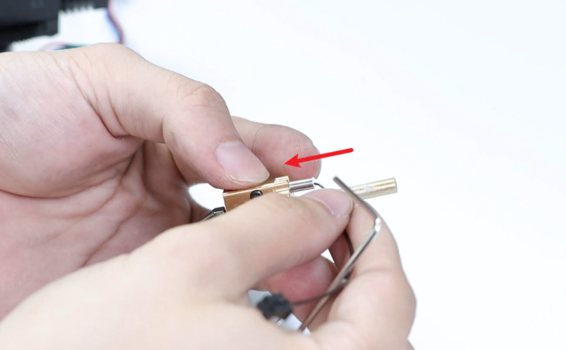
- Adjust the position of the thermal element so that it is no closer than the heating block in front, and there is a small gap at the back. It should be positioned in the middle of the heating block. Just tighten the Set screw.
¶ Replacement of 50-tooth plastic gear
¶ When to Replace
The gears are severely worn out.
¶ Video Guide
Click to Jump IR3V2 Replacement of 50-tooth plastic gear Guide
¶ Replace Guide
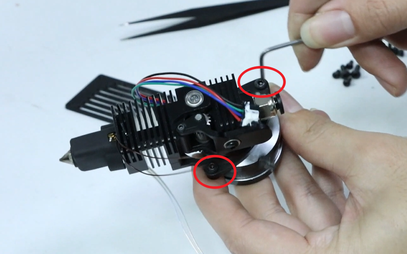
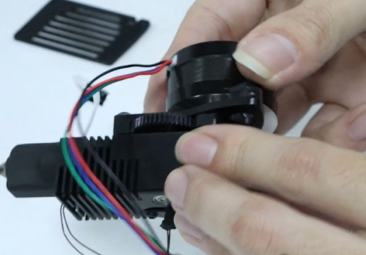
- After disassembly the toolhead, loosen the two screws that fix the motor.
- Take out the motor, loosen the screws at the handle, remove the screws, washers, and the spring and nut on the back.
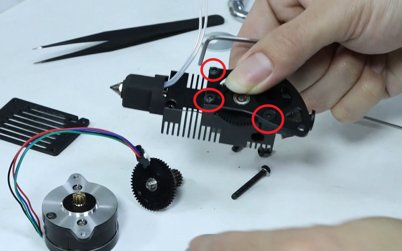
- Loosen the three screws on the fixing plate.
- Take out the fixing plate and the plastic gear, insert the new plastic gear, align it with the bearing hole position, and then place the fixing plate.
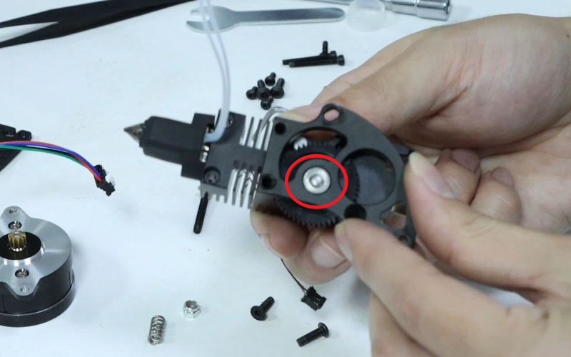
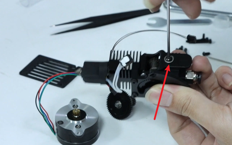
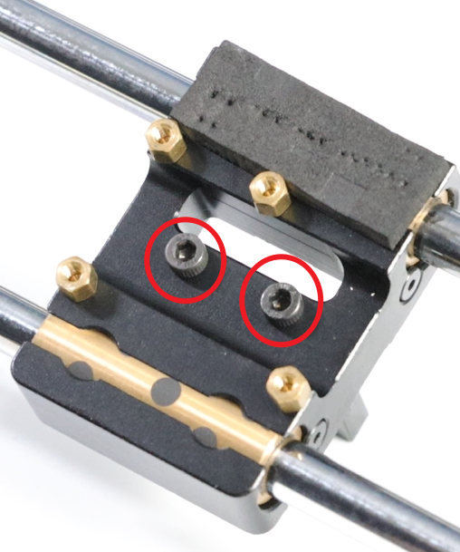
- Lock in 3 screws, adjust the position of the BMG gear up and down so that the plastic gear does not shake up and down when rotating. Lock in the Set screws on the handle side.
- After installing the motor, screw it in (make sure the motor wire points forward), and then adjust the position of the motor.
- Secure it firmly to ensure smooth operation of the plastic gear when it is moved, and then tighten the two screws of the motor.
- Insert the gasket and screws on one side, and on the other side insert the spring and nut. Tighten the screws, making them protrude 2 to 3 turns beyond the nut’s thread.
- Assemble the toolhead back together.
¶ Strain Gauge replacement
¶ When to Replace
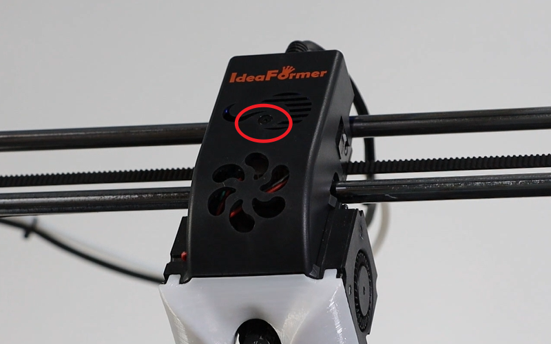
When the Y-axis is home, it stops before touching the conveyor belt, or keeps colliding with the conveyor belt; when pressing the toolhead motor, the blue light does not illuminate.
¶ Replace Guide
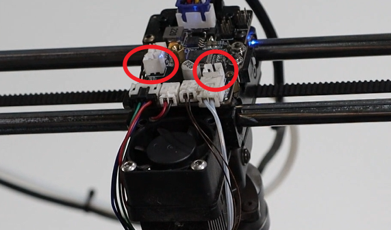
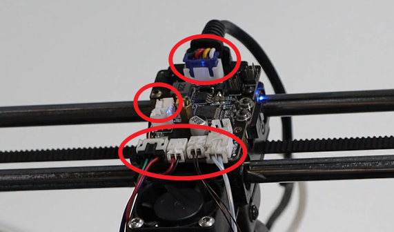
- After disassembly the toolhead, take out the terminals of the strain gauge, the 3015 fan, and the communication terminal of the motherboard.

- Disassembly the screws and Copper pillar.
- Disassembly the two screws beneath the X-axis slider and pull out the terminals of the strain gauge from beneath the X-axis slider.
- After removing the strain gauge, remove the four screws on the 3015 fan. Replace the removed fixing block and the printed part of the air intake plate with those on the new strain gauge. Then screw back the four M3×20 hexagonal screws.
- Move the terminal end of the strain gauge up from beneath the X-axis slider.
- Align the groove beneath the X-axis slider, insert the screws and tighten them. After tightening, slightly shake the strain gauge to check if it is loose.
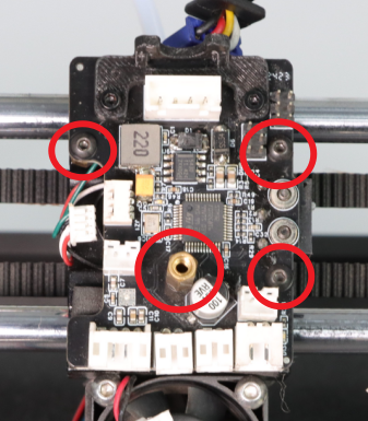
- Put the component back onto the mainboard, screw in the copper column (M2.5×12 + 4) and the screws 3 (M2.5×4 flat-head hexagonal screws), and tighten them.

- After confirming that the strain gauge is not loose, connect the communication line of the mainboard, the insertion end of the 3015 fan to the print head mainboard.

Assemble the toolhead back together.
¶ Replacement of the toolhead mainboard
¶ When to Replace
FAE pointed out that a replacement is needed.
¶ Replace Guide
- Disassembly the flat-head screws at the top of the print head and take off the four cap-head screws at the bottom of the print head housing.


- Disassembly the cover and pull out the fan terminals of the blow mold.
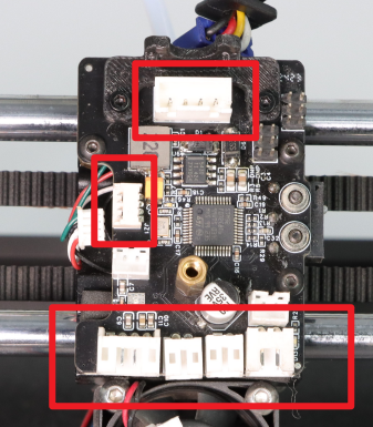
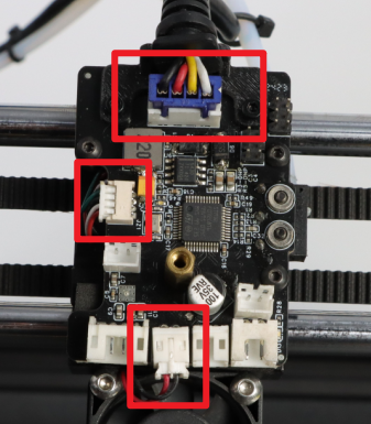
- Disassembly all the terminals on the motherboard, excluding the two blow-molding fans, totaling six terminals.
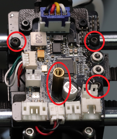
- Disassembly the screws and Copper pillar.

Replace the new motherboard, insert the copper column (M2.5×12 + 4) and the screws (3 M2.5×4 flat-head hexagonal screws) and tighten them.
- Insert each terminal.
- Insert the blow mold fan terminal and position the print head housing precisely into the recess of the motherboard communication line.

- Lock the flat head screws and the four screws at the bottom.

¶ Replacement of X-axis slider
¶ When to Replace
The copper block is severely worn.
¶ Replace Guide
- After disassembly the toolhead, take out the terminals of the strain gauge, the 3015 fan, and the communication terminal of the motherboard.

- Disassembly the screws and Copper pillar. Take out mainboard of toolhead.

- Loosen the 10 screws at the bottom of the X-axis slider, remove the strain gauge and the two synchronous belt mounting plates.
- Loosen the screws of the XY motor, move the motor upwards, and release the synchronous belt.
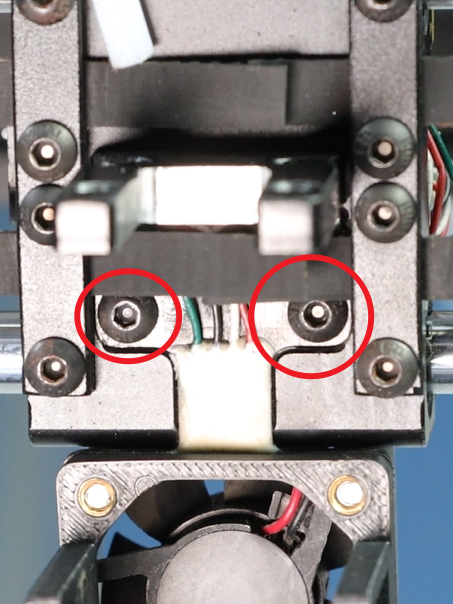
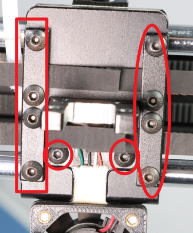
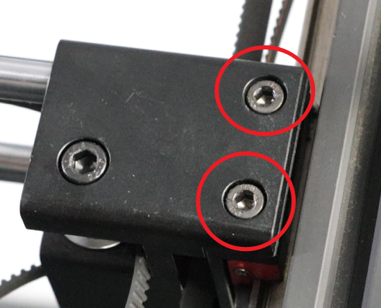
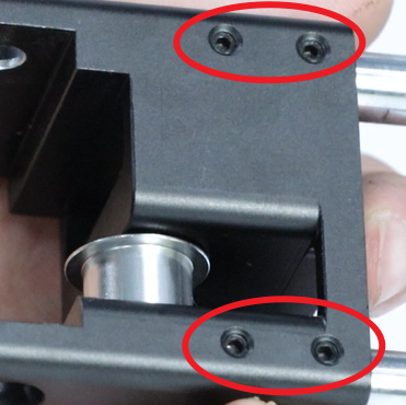
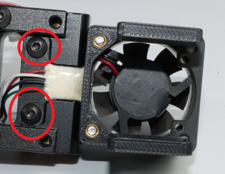
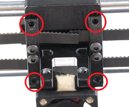
- Disassembly the 8 screws from the X-axis fixing blocks on both sides. The picture below shows the 2 screws on the front side of the right fixing block, and there are another 2 on the back side.
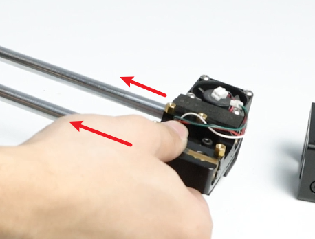
- Disassembly the entire X-axis from the Y-axis slider.
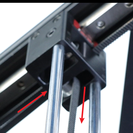
- Loosen the Set screw on the fixed block on one side of the X-axis, so that the optical axis and the fixed block are separated.
- Slide the X-axis slider out, remove the screws on the top, and detach the print head mounting block.
- Install the print head fixing block (2 M3×14 hexagonal screws for the nozzle) and 2 synchronous belt fixing plates (4 M3×8 hexagonal screws for the disc head) onto the new X-axis slider (pay attention to the orientation of the print head fixing block, with the grooved side facing the nozzle, and the side with cotton on the slider.)

- Disassembly e terminals on the strain gauge from the hole beneath the X-axis slider and place them aside. Then align the strain gauge with the slot at the bottom of the X-axis slider and lock it into two M3×4 head hexagonal screws (make sure the strain gauge does not shake after being tightened, otherwise there will be a malfunction when homing the Y-axis).
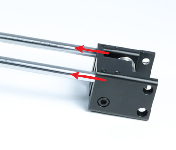
- Place the new X-axis slider onto the optical axis.
- Put the removed X-axis fixing block back onto the optical axis. After reinstallation, move the slider to check if it moves smoothly. You can make the slider move smoothly by rotating the optical axis or loosening the remaining two screws on the X-axis fixing block.
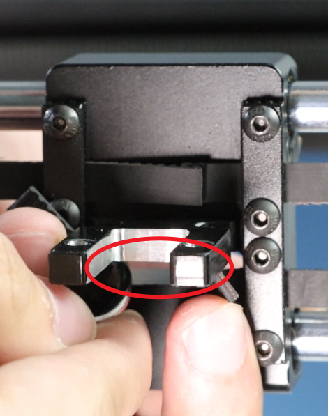
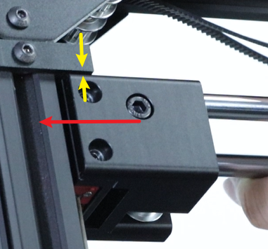
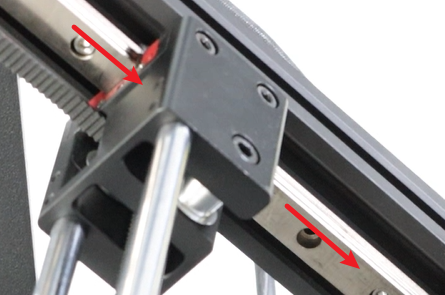
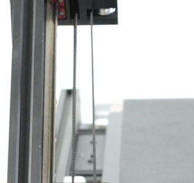
- Reinsert the entire X-axis into the Y-axis slider. Align the screw holes of the X-axis fixing block with the fixing holes of the Y-axis slider, then lock in the screws (8 M4×5 cup head hexagonal screws). At this point, do not tighten yet. Push the X-axis fixing block to both sides to make the X-axis fixing block tightly adhere to the Y-axis slider. Then move the X-axis to the top. Note that there should be no gap between the two fixing blocks and the upper part (as indicated by the yellow arrow in the picture). Press down on the bottom of the fixing block and then lock the screws (pay attention to the direction of the slider, the 3015 fan faces the conveyor belt).
 Move the X-axis slider to check if it is smooth. If it is smooth, lock the base screws. If not, loosen the screws on the other side and then rotate the two optical axes. Then continue to move the X-axis slider until it becomes smooth. Finally, lock the Set screws.
- Reinstall the locking screws (M2.5×4 flat-head hexagonal screws, 3 pieces) on the print head motherboard and the copper posts (M2.5×12 + 4).
- Reference Replacement of the synchronous belt on the x,y axis, After arranging the synchronous belt properly, insert it into the synchronous belt fixing slot and lock it with screws (4 M3×5 head hexagonal screws). Tighten the loosened screws on the XY motor, and straighten the synchronous belt.
- Insert the strain gauge terminals, the 3015 fan terminals and the mainboard line terminals.
Assemble the toolhead back together, After turning on the machine, click the “Auto Leveling” button.
¶ Replacement of the synchronous belt on the x,y axis
¶ When to Replace
Synchronous belt Fracture
The synchronous belt has aged or worn out and has already affected its functionality
¶ Replace Guide
Note: The demonstration here shows the replacement of both synchronous belts simultaneously. If only one belt is to be replaced, please after watching the entire guide before deciding which screws to loosen and how to remove the synchronous belt.
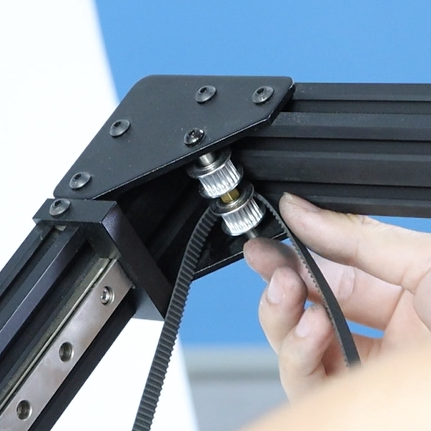
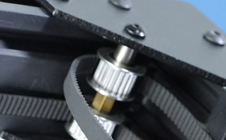
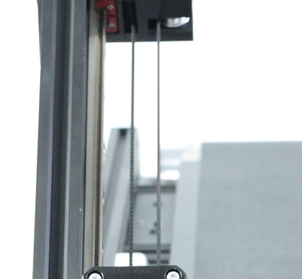
- When passing around the idler wheel and the synchronous wheel, make sure that the synchronous belt is in the middle slot of the synchronous wheel.
- After disassembly the toolhead, Loosen the four screws at the bottom of the X-axis slider
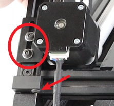
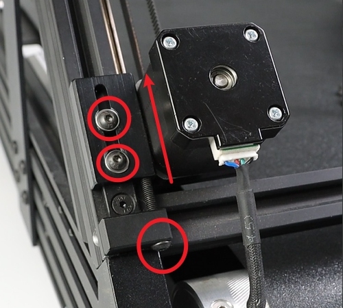
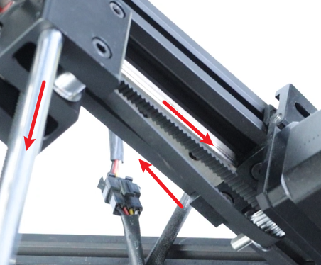
- Loosen Three screws on each of the left and right motors, then move the motors to the topmost position. The picture below shows the left motor.
- Remove the synchronous belt from the slot.
- Fold up the two old synchronous belts, take out a new one, approximately 169 cm long and 6 mm wide, and pass it through the left upper idler wheel.
- Pass through the fixed block on the left X-axis
Return to the X-axis fixed block by bypassing the lower left synchronization wheel.
Pass around the idler wheel inside the fixed block on the left X-axis
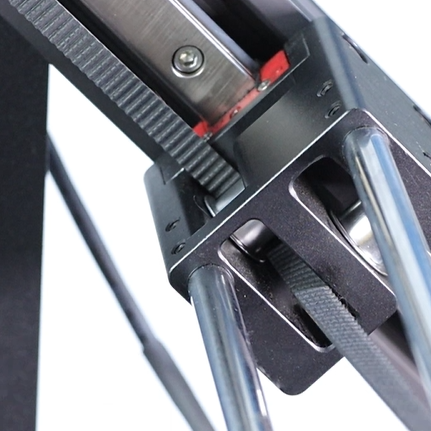
- Insert into the slot of the synchronous belt. When inserting, be careful not to let the end of the synchronous belt exceed too much beyond the slot. It is best to position it in the middle of the two slots. If insertion is difficult, you can use a flat-head screwdriver to slightly pry open the entrance before inserting again.
- Return to the other end of the synchronous belt and pass through the idler wheel on the upper right corner.
Insert into the right X-axis slider and pass around the idler wheel
- Lift the left motor up and move it to the top position. Then, when inserting it into the slot of the other side’s synchronous belt, be sure not to push the synchronous belt too far into the slot. It’s best to keep it in the middle of the two slots.
- Now a conveyor belt has been installed. Next, we will install the second one. It’s similar to the first one. We will then take another conveyor belt and pass it around the idler wheel from the upper left corner.
Insert into the left X-axis slider and pass around the idler wheel
The other side of the synchronous belt passes around the idler wheel from the upper right corner.
Pass through the fixed block on the right X-axis
Pass around the lower right synchronization wheel and return to the X-axis fixed block, then pass around the idler wheel.
Lift the right motor and insert the two ends of the synchronous belt into the slots.
- Tighten the four screws until the card plate deforms under the force.
At this point, the synchronous belt should be loosely and loosely attached.
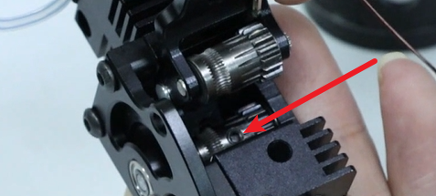
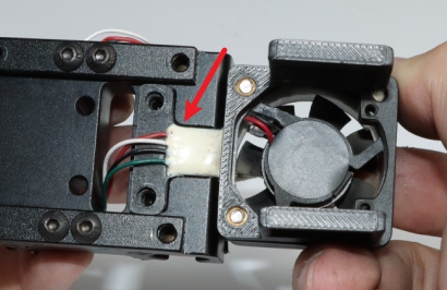
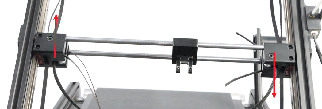
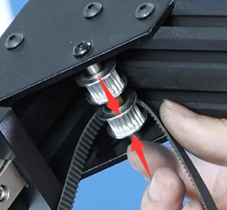
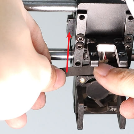
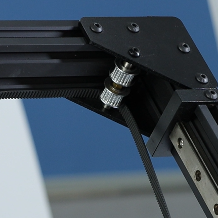
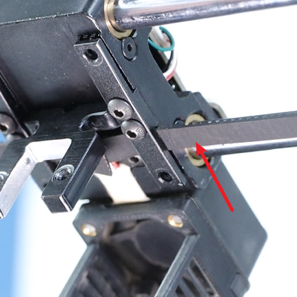
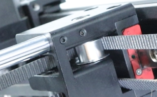
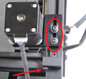
- First, tighten the screws at the arrow position until they are fully tightened, causing the motor to slide a short distance. Then, tighten the two screws in the ring to straighten the synchronous belt.
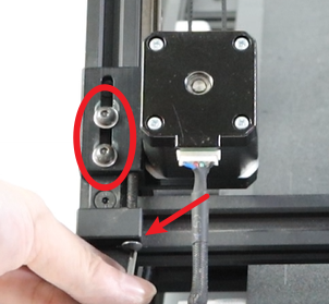
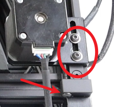
Similarly, at the right motor, the screws at the arrow position should be tightened first, followed by the two screws in the circle, to straighten the synchronous belt.
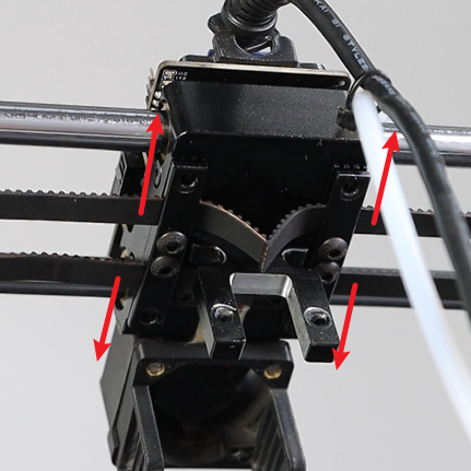
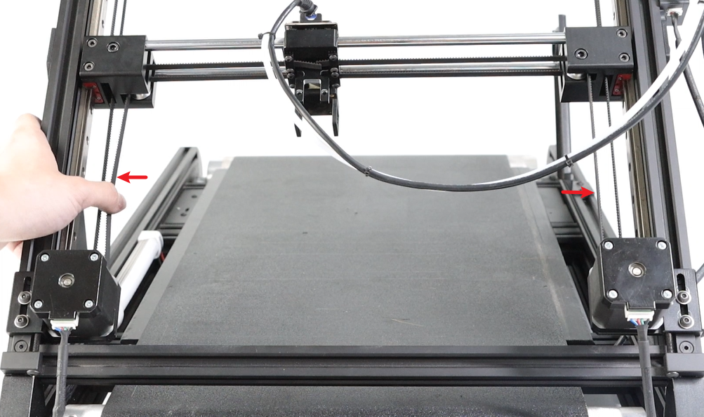
- Move the print head to the middle of the Y-axis, press the synchronous belts on both sides, and check if the pressure on both sides of the synchronous belts is similar. If they are not similar, refer to Leveling Guide to correct the synchronous belts.
- Assemble the toolhead back together, After turning on the machine, click the “Auto Leveling” button.