¶ Strain Gauge replacement
¶ When to Replace
When the Y-axis is home, it stops before touching the conveyor belt, or keeps colliding with the conveyor belt; when pressing the toolhead motor, the blue light does not illuminate.
¶ Replace Guide
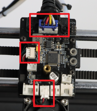
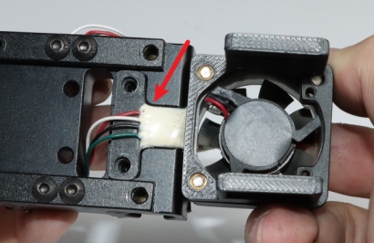
- After disassembly the toolhead, take out the terminals of the strain gauge, the 3015 fan, and the communication terminal of the motherboard.
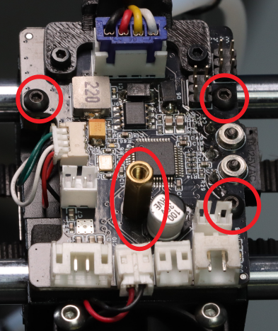
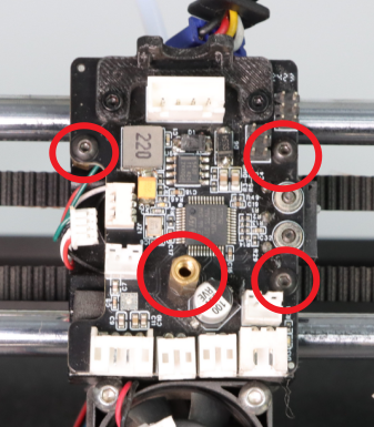
- Disassembly the screws and Copper pillar.
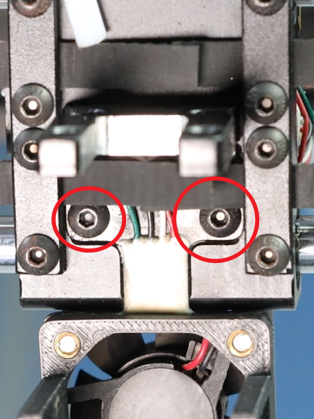
- Disassembly the two screws beneath the X-axis slider and pull out the terminals of the strain gauge from beneath the X-axis slider.
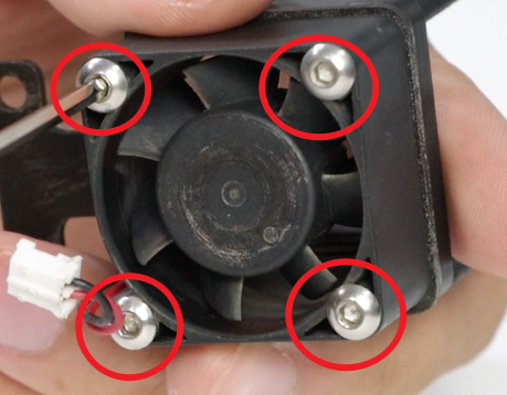
- After removing the strain gauge, remove the four screws on the 3015 fan. Replace the removed fixing block and the printed part of the air intake plate with those on the new strain gauge. Then screw back the four M3×20 hexagonal screws.
- Move the terminal end of the strain gauge up from beneath the X-axis slider.
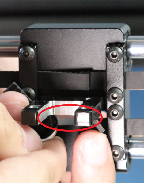
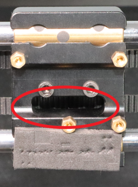
- Align the groove beneath the X-axis slider, insert the screws and tighten them. After tightening, slightly shake the strain gauge to check if it is loose.
- Put the component back onto the mainboard, screw in the copper column (M2.5×12 + 4) and the screws 3 (M2.5×4 flat-head hexagonal screws), and tighten them.
- After confirming that the strain gauge is not loose, connect the communication line of the mainboard, the insertion end of the 3015 fan to the print head mainboard.

Assemble the toolhead back together.